Linkages – Watts Straight Line 51016
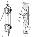
Watt’s straight-line generator, can describe a short vertical straight line. Equal length links AB and CD are hinged at A and D, respectively. The midpoint E of connecting link BC traces a figure eight pattern over the full mechanism excursion, but a straight line is traced in part of the excursion because point E diverges to the left at the top of the stroke and to the right at the bottom of the stroke. This linkage was used by Scottish instrument maker, James Watt, in a steam-driven beam pump in about 1769, and it was a prominent mechanism in early steam-powered machines.

Watt’s linkage consists of a chain of three rods, two longer and equal length ones on the outside ends of the chain, connected by a short rod in the middle. The outer endpoints of the long rods are fixed in place relative to each other, and otherwise the three rods are free to pivot around the joints where they meet. Thus, counting the fixed-length connection between the outer endpoints as another bar, Watt’s linkage is an example of a four-bar linkage.
Link ratios are: L1 = L3. Point P is in the middle of L2
In this example: L1=4, L2=2, L3=4, P= in the middle of L2
Simulation of Watts Straight Line
Warning : Flash Animation May not Work on Some Browsers and Mobile Platforms !