DIRECTION FINDING – 21040
Direction finding is a means of location and/or navigation, usually employing radio or acoustic waves. At radio frequencies (RF), location and navigation systems operate between a few kilohertz and the microwave region. Acoustic systems use frequencies between a few hundred hertz and a few hundred kilohertz.

Signal comparison
A mobile robot can find its position by comparing the signals from two fixed stations whose positions are known, as shown in Fig. 1.By adding 180° to the bearings of the sources X and Y, the robot (square) obtains its bearings as “seen” from the sources (dots). The robot can determine its direction and speed by taking two readings separated by a certain amount of time. Computers can assist in precisely determining, and displaying, the position and the velocity vector.
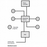
Figure 2 is a block diagram of an acoustic direction finder. In this case the acoustic waves are ultrasound. The receiver has a signal-strength indicator and a servo that turns a directional ultrasonic transducer. There are two signal sources at different frequencies. When the transducer is rotated so the signal from one source is maximum, a bearing is obtained by comparing the orientation of the transducer with some known standard such as the reading of a magnetic compass. The same is done for the other source. A computer uses triangulation to figure out the precise location of the robot.
Radio direction finding (RDF)
A radio receiver, equipped with a signal-strength indicator and connected to a rotatable, directional antenna, can be used to determine the direction from which signals are coming. Radio direction finding (RDF) equipment aboard a mobile robot facilitates determining the location of a transmitter. RDF equipment can be used to find the location of a robot with respect to two or more transmitters operating on different frequencies.
In an RDF receiver, a loop antenna is generally used. It is shielded against the electric component of radio waves, so it picks up only the magnetic flux. The circumference is less than 0.1 wavelength. The loop is rotated until a dip occurs in the received signal strength.When the dip is found, the axis of the loop lies along a line toward the transmitter.When readings are taken from two or more locations separated by a sufficient distance, the transmitter can be pinpointed by finding the intersection point of the azimuth bearing lines on a map.
At frequencies above approximately 300 MHz, a directional transmitting/receiving antenna, such as a Yagi, quad, dish, or helical type, gives better results than a small loop.When such an antenna is employed for RDF, the azimuth bearing is indicated by a signal peak rather than by a dip.